|
..................Installation.......................
The requirements of the site for placing ZHY-401, ZHY-601 type Press machine
1.1. The unit should be located in a laboratory or clean industrial environment. The machine
should rest on a level and flat surface such that it will support the unit without shaking.
1.2. Never place the unit in a location where excessive heat, moisture, or corrosive materials
are present.
1.3. 1 meter of space to the left and to the right is required for maintenance.
1.4. Ambient temperature 10~40℃.
2.1. AC 380V±10%/50Hz, 3-phase+earth, 10A
2.2. Power supply lead section≥1.5mm2, earth lead section≥1mm2.
2.3. For power supply, fluctuation of voltage≤10%, fluctuation of frequency≤0.5%, grounding
resistance of ground wire≤10Ω.
〈Attention〉The protective grounding wire MUST be installed.
2.4. The length of unit power cable is 3 meters.
〈Warning〉Before installing the cable of the unit, be sure that the Breaker is OFF.
3. 1. Fill the tank with YB-N46 anti-wear hydraulic fluid. The fluid should be filled just
above the middle level of the indicator.
3. 2. Before installation, check the machine for damage and loose parts.
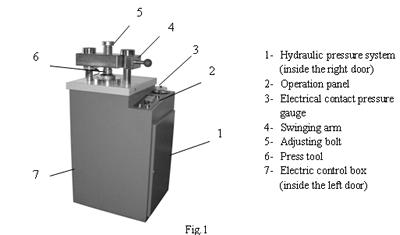
3. 3. Adjust the electrical contact pressure gauge, setting the lower limit to 3 tons and the
upper limit to 10 tons. Screw the adjusting bolt (Figure 1, 5) to the highest position.
3. 4. Without the press tool in place, turn on the power supply. Turn on the breaker located on
the left door of the machine casing. The indicator light in the operation panel is on.
3. 5. While pushing the lifting button or the falling button, observe the hydraulic cylinder
piston rod, the piston rod will move up or down. If the motor is started and the piston rod
does not move, the motor is most likely to be reversed. Please turn off the power and rewire
the power cables.
3. 6. If operation is normal, keep pushing the lifting button and observe the pointer of the
electrical contact pressure gauge. The cylinder piston should move up. As soon as the pointer
begins to move up, immediately release the button. The piston should move up to the top-end of
the cylinder. Now push the falling button until the piston moves down the bottom-end (and the
pump noise begins changing). Release the button. Repeat the above steps three times to deflate
the cylinder.
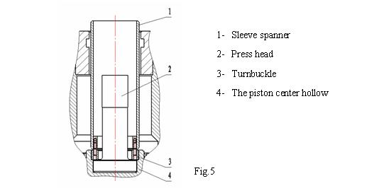
4. Press tool installation
4. 1. Setting up the press head (Figure 5,2). The cylinder piston is fully lifted. Clean up
the facet in the piston center hollow (Figure 5,4) and the press head pedestal surface. Put
the press head (Figure 5,2) pedestal surface into the hollow carefully. Tighten the turnbuckle
(Figure 5,3) using the sleeve spanner (Figure 5,1).
4. 2. Setting up the outer sleeve. The press head starts down to the bottom-end. Carefully put
the outer sleeve into the nesting and rotate it clockwise 90 degrees. The outer sleeve setup is
complete.
4. 3. Carefully push lifting button until the press head moves smoothly into the outer sleeve
hole.
〈Attention〉Boric acid, aluminum cup, steel ring and plastic ring tools are different from
each other. Follow specified installation instructions carefully.
...............Running and adjusting................
1. For Boric acid sample
1. 1. Install boric acid press tool. Turn the program switch (Refer 2, Fig.4) in the PCB in the
electric control box to the left.
1. 2. Adjust the upper limit of the electrical contact pressure gauge (Refer 3, Fig.1) to the
required value (15 tons). The lower limit may keep about 3T. Adjust the press hold timer (refer
4, Fig.2) to the required value (2 minutes).
1. 3. Turn on the power supply; turn on the breaker on the left door. The indicator light on
the operation panel should be on.
1. 4. Boric acid sample instructions:
Close the swinging arm -- Push the start button --Press head will move upward quickly --Do not
begin pressurization until the pressure reaches the lower pre-set limit-- The machine does not
shut down until the pressure reaches the upper pre-set limit.-- Keep pressure constant and set
the timing--When the time reaches 0, the system is unloaded --Open the swinging arm manually--
Push the start button again --The press head moves up jacking up the cover and the sample --
The press head moves down fast --This action does not stop until the setting de-tool time
reaches 0. The program ends.
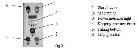
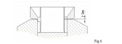
1. 5. Adjust the falling space of the press head:
① Open the swinging arm (refer 4, Fig.1), Push the start button (refer 1, Fig.2); The press
head moves up to the top, and moves down slightly; then the press head stops.
② Put the funnel in the Boric acid tool, adjust the timer (refer 6, Fig.4) of the PCB to make
sure the falling space is 1―2 mm. Refer Fig.6
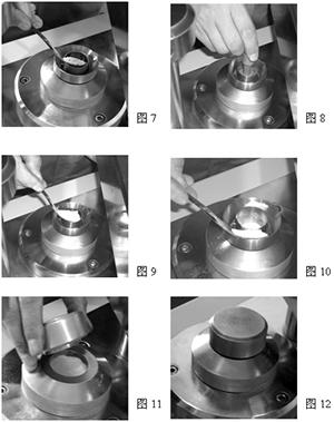
1. 6. Fill sample in the central hole of the boric acid tool. Refer Fig.7
1. 7. Pack the sample down using jig. Refer Fig.8
1. 8. Fill Boric acid in the central hole and the circumference of the funnel. Refer Fig.9,
Fig.10.
1. 9. Remove the funnel carefully.
1. 10. Keep the cover in place. Refer Fig.11, 12.
1. 11. Close the swinging arm.
〈Attention〉When closing the swinging arm do not allow adjusting bolt to touch the cover.
1 .12. Tighten the adjusting bolt (refer 5, Fig.1) to make its lower plane contact the cover
gently.
1. 13. Push the start button (refer 1, Fig.2) to begin automatically running program.
〈Attention〉If any abnormity occurs while running the program, immediately push the stop
button, exit the running program and stop the machine.
1. 14. Keep the falling button held down for one second, unload the remnant pressure.
1. 15. Unscrew the adjusting bolt and open the swinging arm.
1. 16. Push the start button again. The press head will move up jacking up the cover and the
sample. Take off the cover and remove the sample.
2. Aluminum cup sample
2. 1. Install aluminum cup press tool. Turn the program switch in the printed circuit board
in the electric control box to the left. Switch on the power source, the power indicator will
light.
2. 2. Adjust the upper limit of the electrical contact pressure gauge (Refer 3, Fig.1) to
the required value (15 tons). The lower limit should be about 3T. Adjust press hold timer
(refer 4, Fig.2) to the required value (2 minutes).
2. 3. Aluminum cup sample instructions:
Close the swinging arm ―― Push the start button ―― Press head moves upward quickly ―― Do
not begin pressurization until the pressure reaches the lower pre-set limit ―― The machine
does not shut down until the pressure reaches the upper pre-set limit. Keep pressure constant
and set timing―― When the time reaches 0, the system is un-loaded ―― Open the swinging arm
manually ―― Push the start button again ―― The press head moves up jacking up the cover and
the sample ―― The press head moves down quickly ―― The action does not stop until the
setting de-tool time reaches 0. The program ends.
2. 4. Put the aluminum cup in aluminum cup press tool, fill the aluminum cup press tool with
the sample. Refer Fig.
2. 5. Keep the cover in place. Refer Fig..
2. 6. Close the swinging arm.
〈 Attention 〉When closing the swinging arm do not allow adjusting bolt to touch
the cover.
2 .7. Tighten the adjusting bolt (refer 5, Fig.1) to make its lower plane slightly touch the
cover.
2. 8. Push the start button (refer 1, Fig.2) to begin automatically running program.
〈 Attention 〉If any abnormity occurs while running the program, immediately push the stop
button, exit running program and stop the machine.
2. 9. Keep the falling button held down for one second, unloading the remnant pressure.
2. 10. Unscrew the adjusting bolt and open the swinging arm.
2. 11. Push the start button again, the press head moves up and jacks up the cover and the
sample. Take off the cover and remove the sample.
3. 1. Install steel ring press tool. Turn the program switch in the printed circuit board in
the electric control box to the right. Switch on power source, the power indicator is lit.
3. 2. Steel ring sample instructions:
Close the swinging arm ―― Push the start button ―― Press head moves upward quickly ―― Do
not begin pressurization until the pressure reaches the lower pre-set limit ―― The machine
does not shut down until the pressure reaches the upper pre-set limit. Keep pressure constant
and set timing―― When the time reaches 0, the system is un-loaded ―― Open the swinging arm
manually ―― Push the start button again ―― The press head moves up jacking up the cover and
the sample ―― The press head moves down quickly ―― The action does not stop until the
setting de-tool time reaches 0. The program ends.
3. 3. Check the inner diameter of the steel ring: Put the steel ring into positioning hole
of the outer sleeve. Push the lifting button. The press head should enter into the steel ring.
If not, the steel ring is out of use. All steel rings should be carefully inspected before use.
3. 4. Adjust electrical contact pressure gauge with upper limit to required value. The lower
limit should be about 3T. Adjust press hold timer (Refer 4, Fig 2).
3. 5. ?Put the steel ring in place. Adjust the position of the press head using the lifting
and falling buttons appropriately.
3. 6. Charge and put on the cover. Close the swinging arm. Tighten the adjusting bolt. Push
the start button. The steel ring sample program will begin. After the program ends loosen the
adjusting bolt (additional tools may be necessary). Open the swinging arm. The steel ring
sample can be removed. If any abnormity occurs, immediately push the stop button. The running
program will exit and the machine will stop.
3. 7. Adjust the slow pressurizing speed and the delay-time according to trial running
condition:
1)Adjust the pressurizing speed using the slow pressurizing adjusting button (Refer 1, Fig 3)
in the hydraulic system. The slow-pressurizing speed should be adjusted to a faster value to
prolong the life of hydraulic fluid.
2)Adjust the unloading time after pressurizing (see 6, Fig. 4). Normally it is 1 to 2 seconds.
3)Adjust the slow-decompression time (see 4, Fig.4) to ensure the quality of the sample.
4)Before beginning the next operation, adjust the fast de-mold time (see 5, Fig.4) to stop the
press head in a proper position so that it is ready for the next operation.
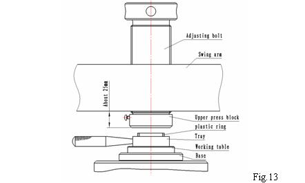
4. 1. It is necessary to clean up the interfaces before using the plastic ring tool. Put the
plastic ring tool pedestal into the outer sleeve. The upper block of the plastic ring tool is
put onto the lower surface of the adjusting bolt.
4. 2. Install plastic ring sample tool. Turn the program switch in the printed circuit board in
the electric control box to the right. Switch on power source, the power indicator is lit.
4. 3. Adjust fast de-mold time; the plastic ring tool pedestal should be removed at the end of
the operation when the machine stops precisely.
〈Attention〉Do not run the machine without plastic ring or without charging.
Prevent hard-to hard extrusion between the tool surfaces or the tool will damage.
4. 4. Plastic ring sample instructions:
Close the swinging arm ―― Push the start button ―― Press head moves upward quickly ―― Do
not begin pressurization until the pressure reaches the lower pre-set limit ―― The machine
does not shut down until the pressure reaches the upper pre-set limit. Keep pressure constant
and set timing―― When the time reaches 0, the system is un-loaded ―― Open the swinging arm
manually ―― Push the start button again ―― The press head moves up jacking up the cover and
the sample ―― The press head moves down quickly ―― The action does not stop until the
setting de-tool time reaches 0. The program ends.
4. 5. Adjust the upper limit of the electrical contact pressure gauge (Refer 3, Fig.1) to the
required value (15 ton). The lower limit should be about 3 ton. Adjust press hold time (refer
4, Fig.2) to the required value (2 minutes).
4. 6. Close the swinging arm (refer 4, Fig.1). Adjust the adjusting bolt to make sure the space
between Upper press block with Swing arm (about 25 mm. Refer Fig.13).
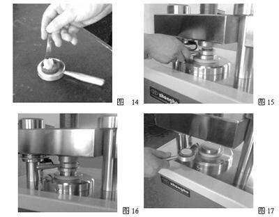
4. 7. Put the plastic ring on the center of tray, fill the plastic ring with the sample. Refer
Fig.14
4. 8. Put the tray and plastic ring with sample on the working table. Refer Fig.15
4. 9. Push the start button (refer 1, Fig.2) to begin automatically running the program. Refer
Fig.16
〈Attention〉If any abnormity occurs while running the program, immediately push the stop
button, exit the running program and stop the machine.
4. 10. Take out tray and plastic ring sample. Refer Fig.17
4. 11. Check the position of the working table to make sure that there is no space between the
working table and the base, and that the pump still runs for 1~2 seconds. Otherwise adjust the
timer (refer 5, Fig.4) in PCB.
|