|
...................Installation......................
1. Location
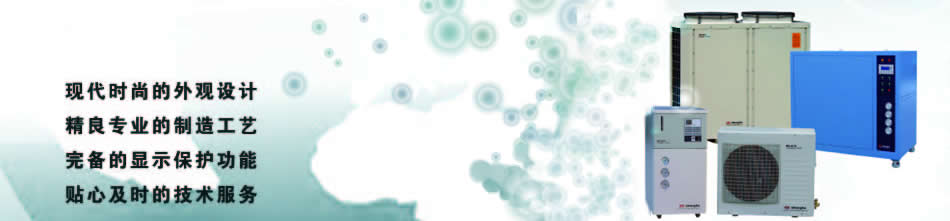
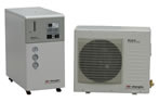
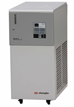
The requirements for location of the BLK-x FF-B series water chiller:
1.1. The unit should be located in a laboratory or clean industrial environment.
1.2. Never place the unit in a location where excessive heat, moisture, or corrosive materials
are present.
1.3. The unit has an air-cooled refrigeration system. It must be positioned so the air intake
and discharge are not impeded.
1.4. Outside ambient temperature < 40℃.
2.1. Power supply lead section≥2.5mm2, earth lead section ≥1.5mm2. (-5FF, -12FF)
Power supply lead section≥4.0mm2, earth lead section ≥2.5mm2. (-8FF)
2.2. For power supply, fluctuation of voltage ≤10%, fluctuation of frequency ≤0.5%, grounding
resistance of ground wire ≤10Ω.
CAUTION! It must install the protective grounding wire.
2.3. The length of unit power cable is 3 meters.
CAUTION! Before installing the power cable of the unit, assure the Breaker (18) is in OFF
position and the power supply is OFF.
CAUTION! The refrigeration circuits and electrical circuits of unit must be installed by
professionals.
3.1. Determine the installation site of machines both for indoor installation and outdoor
installation
3.2. Height of outdoor unit should not be more than that of indoor unit, and the indoor unit
should be located as close to the outdoor unit as possible.
CAUTION! Once the installation of water chiller is finished, both the indoor unit and outdoor
unit can not be moved.
3.3. In order to connect the indoor unit with outdoor unit by copper tube and cable, a circular
hole that is 100~500mm in diameter should be drilled in the wall at a distance of 200mm from
the ground surface. (This hole is used for pulling the copper tube and cable from indoor to
outdoor.)
3.4. Assemble the support brackets for outdoor machine. Drill holes for expansion bolts into
wall two feet apart (horizontally). Insert the expansion bolts into the support brackets and
drive them into the bolt holes completely by hammer. Screw on the nut with wrench; make sure
that the outdoor machine is within two feet of indoor machine, complying with specifications.
Finally, put the outdoor machine on the outside part of support brackets and screw in fixed
bolts.
3.5. Unfold the copper tubes and adjust the relative position between two copper tubes
according to the connecting joints on the indoor machine. Bundle the two copper tubes together.
Pull the cable 1 for connecting indoor machine and outdoor machine through the hole in wall,
then pull the bundled copper tubes though the hole, make sure an appropriate length of cable
and copper tubes are inside the room, and the rest are laying outside the room, which shall be
coiled together carefully. Make sure the head of outdoor copper tube is aligned to the
direction of foot valve. There should not be any kinks; the outdoor copper tube shall be laid
behind the outdoor machine, making sure the outdoor copper tube can not be seen from the front
view of outdoor machine.
3.6. Adjust the adapter of copper tube to make it aligned to the direction of connecting joints
on indoor unit. Put rubber pad under the feet of indoor unit, then turn the feet until they
completely contact with the rubber pad.
3.7. Align the pipe socket of copper tube to the adapter, screw in the nut first by hand, then
by wrench. In the same way, screw in the nut of outdoor copper tube.
3.8. Unscrew high-pressure valve and low-pressure valve caps. Unscrew low pressure filling
valve cap. Push in on the filling nozzle pin of low pressure valve using an Allen wrench to
release gas. Connect filling hose to low pressure filling nozzle. Open high pressure valve
CAUTION! At this time, gas will release from the filling hose connected to the low pressure
filling nozzle for about 10-20 sec.
3.9. When gas stops releasing, unscrew filling hose. Now, open low pressure foot valve. Coat
threads of low pressure foot valve with refrigerant sealant, a few drops should be sufficient.
Screw the low pressure valve cap on by hand, and then tighten with a wrench. Repeat the last
step with the low pressure filling nozzle. Now, repeat the past two steps with the high
pressure valves (pressure valve and filling nozzle).
3.10. Carefully examine any place (adaptor, high-low pressure valve, filling opening, and nuts)
where gas leakage may exist. If any gas leaks are detected at any place, remedy any leakage
immediately.
3.11. Open the junction box of outdoor unit and connect cable according to the labels of wires.
In addition, make sure all screws on block terminals have been tightened firmly and then
tighten up the screws on junction box of outdoor unit.
3.12. Connect power supply.
CAUTION! Before connecting power supply line, make sure the operating switch of water chiller
is in the “stop” position.
4.1. Remove the fixed bolts on the base of water pumps.
4.2. Remove the pipe between water supply (1) and water return (2), and connect the water pipe
from the water supply (1) of the water chiller to the IN of the water filter (or equivalent).
The OUT of the water filter (or the equivalent) is connected to the inlet of the equipment. The
outlet of the equipment in connected to the water return (IN) of the water chiller.
4.3. If there is water filter (optional) in water chiller, the water outlet of water chiller
shall be connected with the water inlet (IN) of filter, and the water outlet (OUT) of filter
shall be connected with the water inlet of equipment, meanwhile, the water outlet of equipment
shall be connected with the backwater of water chiller.
4.5. All joints between hose and adaptor should be fastened by appropriate hose clamps.
4.6. Try to reduce the length of water tube between water chiller and equipment. Extra lengths
of water tube will have a negative impact on the accuracy of the water temperature and will
also reduce the water pressure. If a long length of water supply is necessary, use hard water
tubing with thermal insulation and use a short hose to connect the hard tube to the water-
cooled machine.
5.1. Remove the top plate (11).
(There are 2 screws in front, and 2 screws in back of the plate.)
5.2. Remove the Tank cover. (13)
5.3. Fill the tank with pure distilled water until the water level indication (6) reaches the
High level.
5.4. If water filter is installed correctly, press the red air release valve on the water
filter and hold until the air is released completely and the water begins to discharge; then
release the red air release valve.
5.5. Refill the distilled water after the water chiller is connected and operated with the X-
ray generator until the water level indication (9) reaches the High level.
Water quality
1) Fill with pure distilled water, the water temperature should be between 8℃ and 35℃.
2) DO NOT mix flammable or corrosive liquid in the water.
5.6. To prevent the growth of algae in the tank (15), please keep tank cover (13) in place.
............Operating instructions.................
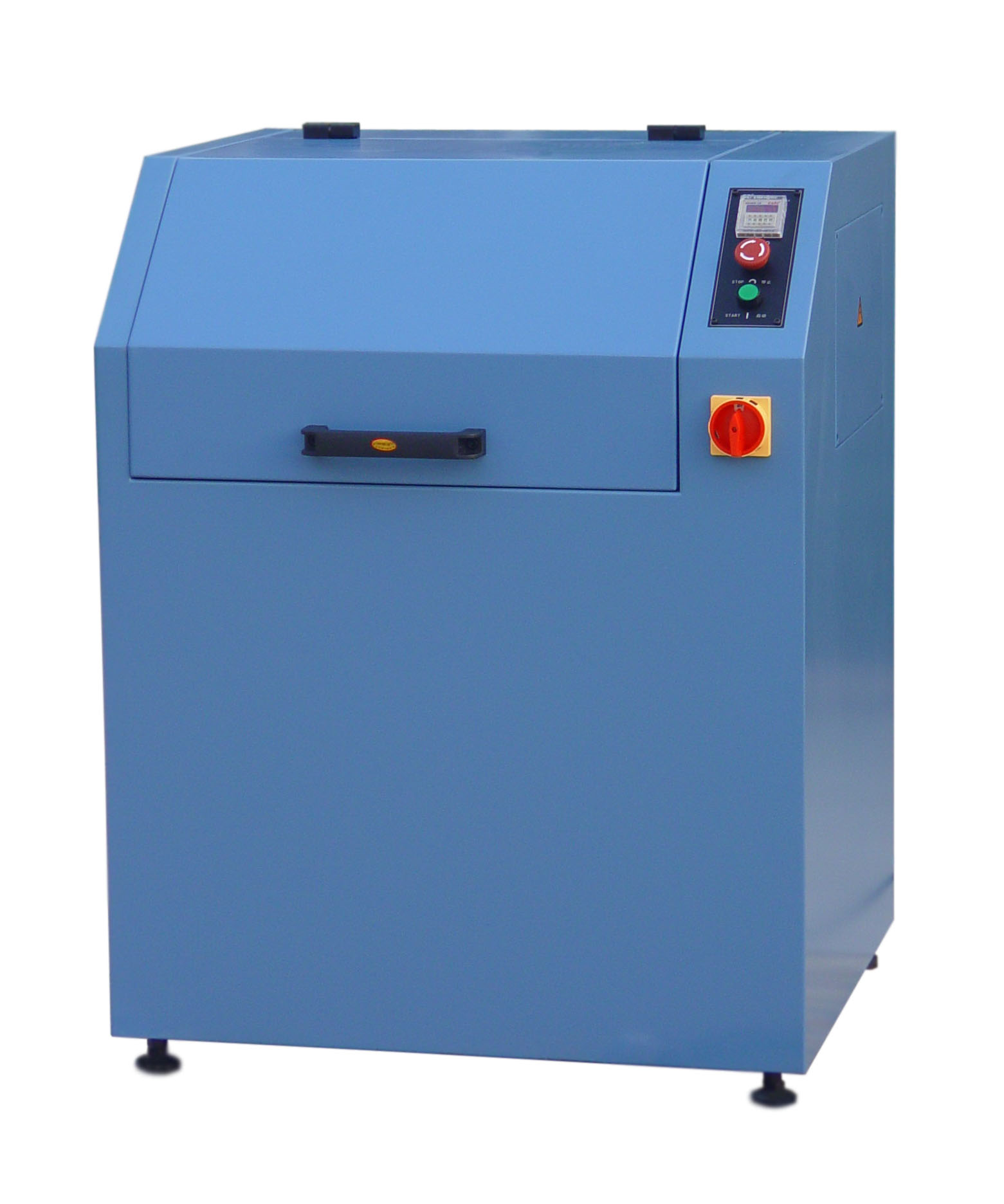
1. Recheck the connection of the power supply and water pipes before operating the water
chiller. Be sure that the operating switch (9) is in the STOP position.
2. Open the water supply valve (1) and water return valve (2). Adjust the water bypass valve
(14) to the neutral position (in between ON and OFF).
CAUTION! The bypass valve (14) must NOT be closed completely, otherwise the water pump may be
damaged.
3. Switch on the breaker (18) and turn the operating switch (9) to RUN. The power LED will
light up. The thermostat (8) mode indicators are lit sequentially from the left during a 6
second period indicating the thermostat is operational. (Alarm temperature LED will light as
well, but this is normal.)
4. Then, when the water pump is running and the water pressure gauge (3) has indication, watch
the indication of the water pressure gauge (3); adjust the bypass valve (14) to the required
water pressure of equipment; and check for any leakage.
5. Use 〔∠〕,〔∨〕,〔∧〕 keys to adjust the temperature setting. When no keys have been
pressed for 2 sec. or longer, the flashing numeric value will stop, indicating the new
temperature setting.
6. After the pump runs for 4 minutes, when the actual water temperature is 4℃ higher than the
water temperature setting, the compressor will start. The refrigerating system is now
operating; the water chiller is in the Cooling status (Cooling LED is ON). When the actual
temperature is lower than the water temperature setting, the compressor will stop. (Cooling LED
is OFF).
7. The High pressure regulator controls the starting and stopping of the fan. When the pressure
is higher than 1.4MPa, the fan starts; when the pressure is lower than 1.0MPa the fan stops.
8. Refill the tank with distilled water until the water level indication (6) reaches the High
level; keep tank cover (13) in place.
|